🔧 Build Your Connection with the ATU-100!
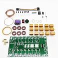
The Malahit ATU-100 Antenna Tuner DIY Kit is a cutting-edge automatic tuner designed for frequencies between 1.8-50MHz. It features a compact 0.96-inch OLED display for clear data visibility and is built with high-quality components, including 1000V SMD capacitors. The kit comes with pre-soldered parts and easy-to-follow instructions, making it an enjoyable project for both beginners and seasoned enthusiasts.

| Color | Multicolor |
| Number of Channels | 1 |
| Impedance | 50 Ohm |
| Maximum Range | 1000 Meters |
J**R
Fun afternoon build
Bought this on a whim since I wanted another kit to work on. The price for this unit was attractive and I always wanted a little auto tuner, so why not!Took a couple hours of casual building. The provided instructions aren't great, so if you've never built anything like this before, you may have a couple difficult points. Specifically, the binocular torroid winding for the primary and secondary. It is not well explained or shown on the provided instruction piece of paper. Most of the soldering is pretty easy with a decent fine tip iron (don't go trying this with a soldering gun or something lol)Fired right up the first time and worked perfectly. Fun and useful kit. Can't believe the price.
J**M
Great little QRP tuner.
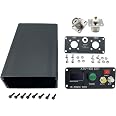
Great little QRP antenna tuner, tunes just about any antenna. Shame it's only rated for 100 watts and to be honest, I don't it will handle more than 50 watts. As for building the kit goes, it's really easy, the only thing you will have trouble with is winding the binocular ferrite. I also recommend using some magnet wire for this, the plastic wire they give you will move out of place as you are winding it as where magnet wire will stay in place better. Don't waste money buying the matching case for it, find something else to put it in, save some money.
S**I
Great Kit But Not For First Time Kit Builders
I FINALLY got this ATU-100 Antenna Tuner kit built after watching several YouTube videos done by previous builders. The Tuner works great but I had to re-work some wiring errors I made due to the lack of detailed instructions and the fact that I am not an Electronics Assembly Expert.The difficulty is that there are no detailed Step-By-Step Instructions for this kit. There is adequate information on the document along with the Schematic to enable an experienced kit builder to assemble the kit. However, a relatively new or first-time kit builder probably will not be able to get it assembled.Here are a few things I learned (some the hard way!) -Unless you have SUPER eyesight, use a large magnifying glass/light before you attempt to build this kit.1. For the Malahit ATU-100 Antenna Tuner Box, the image of the wiring on the back of the green TuneSwitch is incorrect. The wire connecting half of the Auto, BYP and Tune switches goes to GROUND, NOTthe + wire as shown in the picture that comes with the Tuner Box. The OTHER side of the Tune switchgets the + wire.2. The hookup wire necessary to fully assemble the ATU-100 kit does NOT come with the kit! You willhave to provide the stranded insulated hookup wire yourself (NOWHERE is this mentioned on AmazonNOR the single Instruction sheet!).A. I used some 18 ga. stranded insulated wire for the initial power connector but the hole in the PCBmade it tough to fit that size wire in the (-)hole. The other wire (+) goes to the On/Off Power Switchso there was no issue there.B. I used 22 ga. stranded insulated hookup wire (very flexible!) for the other hookup wire connectionsthat were necessary.C. The Yellow and White wires needed to connect the Auto and BYP switches to the BACK SIDE of thePrinted Circuit Board (PCB) must be VERY small to fit into the two tiny PCB holes they must besoldered into. You will need to be very careful soldering these two wires to the back of the PCBbecause the solder pads are so small and so close together!3. This is a very compact kit. Use a very small pointed Soldering Iron to prevent overheating the PCB orthe already installed SMD components.4. As another Amazon customer suggested, I recommend building and installing the Toroids FIRST (and intheir numbered order). Trying to install the Toroids AFTER the Relays are soldered onto the PCB will bea nightmare.5. Pay close attention to the size and LENGTH of the wire for each Toroid as stated on the Instructionsheet.6. As suggested in the instruction sheet, I used Allen Wrenches the proper diameter as described to windthe three air core windings.7. Take your time and be sure you understand EXACTLY where each component and wire should besoldered to the PCB. I initially soldered the four light yellow enamelled wires for the Tandem MatchTransformer "binocular" toroid in the WRONG 4 holes (underneath it!). They actually go into the fourSMALL holes just outside the "binocular" toroid's diagram outline on the PCB.8. The Electrolytic Capacitors have a very distinct mark on one side. Be sure that side of those Capacitorsgoes into the PCB hole that shows the white mark on the edge of the circle images on the PCB.9. Examine the picture of the vertically installed diode as it is shown on the Instruction sheet. Be sure thewhite ring mark is at the TOP when you solder it into the PCB (you will have to bend that end of thediode's terminal wire down toward the other wire end to install it vertically).10. If you buy the Tuner Box, BEFORE YOU SOLDER THE SLIP ON TERMINALS ONTO THE OLED, be sureyou draw yourself a diagram showing which terminal on the OLED display module is which connection(i.e., Gnd, VAC, SCL and SDA). After you solder the push-on terminals to the OLED display module, youwill no longer be able to read those markings on it!11. If you buy the Tuner Box pay close attention to how the four green mounting tabs are oriented in thepicture when they are attached to the PCB.12. If you buy the Tuner Box, when pushing the On/Off Power Switch into the end panel, do your best tokeep the switch even and press it straight into the rectangle hole (i.e., NOT one side in before theother!).13. If you buy the Tuner Box, I suggest sticking a piece of electrical tape or other insulation material ontothe back side of the front end panel. This tape will insulate the inside of the front box end panel. Thisis BETWEEN where the OLED display's soldered connectors are located and the inside ofthat box end. This should keep those solder connections from contacting the inside of that metal boxend. The Instruction sheet does not mention this. It just didn't make sense to me to risk those solderconnection points touching the metallic box end panel and potentially shorting out. I actually used asmall file to flatten the sharply pointed solder points to make their thickness narrower and less likelyto punch through the tape and contact the metal end panel.As I said, my completed ATU-100 Tuner works great! However, my language during the build process was not fit for human ears! I hope this was helpful to others considering to buy and build this kit and that they have a much better experience building their kit.73!
T**S
The thing actually works
It's an antenna auto-tuner that works on the HF (shortwave) bands used in Ham Radio. It works fine. The latest firmware version works with as low as one or two watts, with the maximum of 100 watts. No complaints. It's inexpensive, and easy to assemble. BUT! Make certain you have soldering skills and the ability to read electronic assembly instructions.
J**S
Seller doesn't care
Built the tuner, rather straight forward construction. Didn't tune! I did my normal trouble shooting and found bypass relay on all the time. Determined the program IC is defective.Contacted seller, wanted proof it was his device. Sent in pix's of board. Never got any comments back. So back it went to Amazon.Bottom line don't even think of buying from this seller, most dishonest.
K**K
Bought, Built, Used, and I'm happy
Bought this kit for 2 reasons...1. I was bored and wanted to build something2. Was looking for an antenna tuner for POTAFirst and foremost... Great little kit that comes with everything you need to build a functional antenna tuner (Minus the case but thats obvious). I built it in a day and had it functioning in no time. Instead of using the supplied power input i did use Anderson power pole connectors. I went with the power poles for versatility. I can run either a 9v battery to the tuner or connect it to the 12v battery from my power bank. I did need to replace the diodes across the SWR bridge with better schottky diodes... No issues with the diodes on the board but just as a preemptive thing. The tuner tunes decently quick, not as quick as my LDG z100 but pretty close. After building it I 3d Printed a case for it to go into and i have been a happy camper since. Works very well and couldn't ask for anything more. If you're looking for a weekend project or just want the satisfaction of building one of the pieces of equipment you use here it is!WARNING: DO NOT tune with full power... turn your power down to about 10watts or so if your radio is capable of 100watts. I have used as little as 5watts and right around 15w max for tuning. Good luck and have fun!
A**R
Programming Locked - no upgrade path
You will not be able to change or upgrade firmware. Fails to find lowest SWR, but in test mode, manually adjusting LC settings can easily bring down. No issues in building, but do not make this your first kit.
Trustpilot
5 days ago
3 days ago